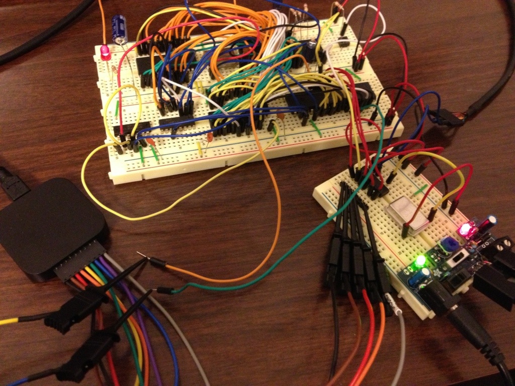
The Project:65 computer. The little board at bottom right holds the MAX3100 UART and its oscillator, along with the power supply. The UART connects to an FTDI cable at upper right. My new logic analyzer is visible at bottom left.
My rush of work on the Project:65 computer over the holidays gave me a “working” system, but it hadn’t done anything more complex than blink a few LEDs. It was time to dig into the input and output, and get this machine to talk to the outside world.
My plan all along had been to use the parallel ports provided by the 6522 VIA. As I described a few weeks ago, I’d come up with a quick and dirty way to bitbang the SPI serial protocol to send text back and forth beween the 6522 and an Arduino, with the Arduino relaying the text to a PC. I prototyped the software on a Commodore 64, and figured that having the Arduino in the middle would make it easier to debug any problems.
The first step was to take the original C64 code and update it for use with Project:65. That mostly entailed moving things around. The program code had to be moved up to P65’s ROM area, starting at $E000, and the VIA was going to be at a different location in memory. One thing I missed initially was that the register addresses for the “A” and “B” parallel ports in the VIA are backwards from how they’re arranged in the C64’s 6526 CIA chip, but that was a trivial change once I noticed it.
The P:65 program also needed a little more initialization that the C64’s KERNAL OS had taken care of. I had to put in a value for the RESET vector up at $FFFC, and direct it to a block of code that would set up the stack pointer, disable interrupts, and initialize the VIA.
All of this would have been straightforward, if I hadn’t run into a bug in CBM Prg Studio. The recent versions apparently have a glitch with how they deal with certain labels, and as a result the assembler was generating incorrect machine code from my source. (I’ve reported the problem to the author, so I expect that’ll be fixed in the next release).
Compiler bugs can be incredibly frustrating, because they’re usually the last thing you think to look for. This is the second time I’ve been bit by CBM Prg Studio. I think it’s time to start considering other options.
After spending too much time debugging (happily I stopped before redesigning my address decoder yet again) I had a simple kernel that could receive text, echo it back and store it in a buffer, and spit it back to me when I pressed return. It didn’t actually process the text at all, but this could be the first step to a command-line interface.
Still, I wasn’t entirely happy about the arrangement. Having the Arduino in the loop felt like a bit of a cheat. I mean, I needed to communicate between a computer and a computer, so I put a computer between the computer and the computer, so I could… oh, never mind. It just seemed kind of silly.
Really, what I wanted for a proper retrocomputing feel was an RS-232-style serial connection, with the P:65 computer talking directly to a terminal program on my PC. I checked online for some suggestions, did some shopping, and in two days had some interesting parts show up in my mailbox.
I purchased a couple options, but the solution I started with – and stuck with, because it’s working pretty well – was a Maxim Max3100 chip. This chip is a UART (Universal Asynchronous Receiver/Transmitter – i.e. something that can speak over a serial connection) with an SPI interface. Basically, it would do what the Arduino had been doing – the P:65 computer talks to it over SPI on the VIA, and then it runs the serial connection to the PC. The advantage of doing something like this is that the 3100 takes care of all the timing to run the serial port. The P:65 CPU only needs to speak SPI, and it can do that at whatever speed is convenient.
One problem I had is that I was running out of breadboard. The 3100 isn’t a very big chip, but it also needs its own oscillator to generate the different baud rates it can run at. There was just enough room on the little breadboard my power supply was hooked to, and I only needed to run 4 SPI signal lines from the VIA on the main breadboard.
There was one other problem on the hardware side – my PC doesn’t actually have a serial port. Neither does my 2005-era laptop. I used to have one of those USB to serial adapters, but I have no idea where it is. Instead, I picked up an FTDI cable from Sparkfun. It’s basically the same as a USB to serial adapter, but for my purposes it has two advantages: First, I could plug my jumper wires directly into it, instead of needing some kind of DB-9 serial port connector; and second, it uses 5 volts for all its signals, instead of the 12 V that regular RS-232 uses. I also had a Max232 chip that’s supposed to deal with the voltage difference, but this way I didn’t have to worry about it.
The best part of this project was that it gave me a chance to play with one of my new toys – a Saleae Logic Analyzer, aka the coolest Christmas present ever (Thanks, Mom!). This thing is so much fun to play with, and it’s also useful. You connect the 8 leads to different places on your circuit, plug the analyzer into your PC’s USB port, and then you can record all the activity in the circuit. The software can even interpret common protocols like SPI.
In the pictures here, I’ve got leads hooked up to the SPI bus between the 6522 and the Max3100. I’m also monitoring a couple other useful signals like the reset line. In the screenshot, you can see the traffic, and it’s even showing the hexadecimal and ASCII values of the data that’s being sent across the SPI bus.
With the logic analyzer showing me exactly what data I was sending to the Max3100 and what the 3100 was sending back, adjusting my software to the 3100 was quick and easy. That would have been a lot harder without it, I’m sure. I wish I’d had this thing a couple weeks ago!

The logic analyzer’s display window. In this image, we’re monitoring the SPI communications while the P:65 computer is transmitting its name on the serial port. We loop on each letter of the message until it is successfully sent.
Every command for the 3100 is a two-byte sequence, with the chip responding simultaneously. For example, if you want to transmit the character “r” (as in the screenshot), you send a command byte (0x80 for “send”) and a data byte (0x72, the ASCII value of “r”. As you send the command, you read the status. In the case of sends, the important status bit is the one that tells you if the output buffer is full or not. I started running the serial bus at 9600 baud, which meant that the 6502 was able to send data much more quickly than the 3100 chip transmitted it. In my first iteration of the software this caused a lot of dropped characters – I’d send “Pjc:5ope” instead of “Project:65 computer”. The simplest fix was to monitor that status bit in the response, and keep sending the same character until I was sure it went through. In the screenshot, you can see two attempts to send the letter “r”, the second of which succeeds. It then starts sending the next character, an “o”.
With an actual asynchronous serial port installed, I feel like I’ve hit another milestone with this project. It’s got most of the hardware features of a real (really primitive) retrocomputer. Now I need to figure out how to get some software onto this machine without rewriting the EEPROM every time.
